How to Draw Free-Body Diagrams: A Step-by-Step Method That Prevents Errors
Most wrong answers in introductory mechanics are decided before any equation is written. The forces were drawn wrongly, a force was missing, or an arrow was included that is not a force at all. Fix the diagram and the algebra usually follows.
A free-body diagram is a simple tool: one object, drawn alone, with every force acting on it shown as an arrow. Its power comes from the discipline it imposes. You must decide what the object is, name each force and what exerts it, and commit to a direction before you touch Newton's second law.
This guide gives a five-step method, works through the standard cases, and lists the mistakes that examiners see most often. It assumes you know what the second law says; if you need that first, read our Newton's laws guide, which introduces these diagrams in context.
Step 1: choose the object and draw it alone
Decide exactly what "the object" is. A box on a ramp, the box and the ramp together, or the person pushing the box are three different systems with three different diagrams. Write the choice down.
Then draw the object by itself. A dot or a small box is enough. Remove the floor, the rope, the wall, and anything else that touches it. Those things will appear only as the forces they exert.
This step is where the "free" in free-body comes from: the body is freed from its surroundings so that every interaction has to be represented explicitly. A diagram that still shows the ramp under the box invites you to forget that the ramp pushes on the box.
Step 2: list every real force and what exerts it
Go through the contacts and the field forces in a fixed order so nothing is missed.
Weight. Every object with mass near Earth has a weight acting straight down, exerted by the Earth. It acts even if the object is not moving.
Normal forces. Every surface the object touches pushes on it, perpendicular to the surface and away from it. A floor pushes up. A wall pushes sideways. A slope pushes perpendicular to the slope.
Friction. Every rough surface the object touches can also exert a force parallel to the surface, opposing sliding or the tendency to slide. Kinetic friction opposes the motion; static friction opposes whatever would happen without it.
Tension. Every rope, string, or cable attached to the object pulls along the rope, away from the object. Ropes never push.
Applied forces. Any push or pull stated in the problem, at the stated angle.
Springs, drag, lift, buoyancy, electric or magnetic forces as the problem requires.
For each force, name the thing exerting it. "Normal force from the floor," "tension from the left rope." If you cannot name the source, the force does not belong on the diagram. That single test removes most invented forces.
Step 3: draw each force from the object, in its real direction
Start every arrow at the dot and point it in the direction the force acts. Longer arrows for larger forces are helpful but not required; direction is what matters.
Label each arrow with a symbol you will reuse in the equations: or , , , , . If two forces of the same type exist, distinguish them: and , and .
Do not draw forces the object exerts on other things. The box pushes down on the floor, but that force acts on the floor, so it appears on the floor's diagram, not the box's. Newton's third-law pairs never appear on the same free-body diagram, because they act on different objects.
Step 4: choose axes that follow the motion
Draw a small pair of axes beside the diagram. Align one axis with the direction of the acceleration, or with the surface if the object moves along one. On a flat floor that is the usual horizontal and vertical. On an incline it is along the slope and perpendicular to it.
The reason is practical. With axes along the slope, the normal force and friction lie exactly on axes, and only the weight needs splitting into components. With horizontal and vertical axes on a slope, three forces need resolving instead of one, and the algebra triples.
If the object is not accelerating, any orientation works, but the same rule still minimises the components.
Step 5: write the second law along each axis
Read the diagram axis by axis. Sum the components along the first axis, set them equal to along that axis; do the same for the second axis. Forces pointing in the negative direction get a minus sign. An axis with no acceleration gets zero on the right-hand side.
Now the diagram has done its work. The equations are a transcription of the picture, not a fresh act of reasoning, and if the picture was right the equations are right.
Solve, then check the result against the diagram. A negative friction force means it points the other way from your arrow. A negative normal force means the surface would have to pull, which it cannot, so the object has left the surface and the model has changed.
Worked case: a box pushed across a rough floor
A 10 kg box is pushed by a horizontal force of 40 N across a floor with kinetic friction coefficient 0.3. Find the acceleration.
Object: the box. Forces: weight down (Earth), normal up (floor), friction opposing motion (floor), applied forward (the push). Four arrows.
Axes: along the push, upward. Vertically, nothing accelerates, so
giving . Horizontally,
with , so .
Notice that the friction depends on the normal force, and the normal force came from the vertical equation. The diagram makes that dependency visible: friction and normal force are two arrows from the same surface.
Worked case: a block on an incline
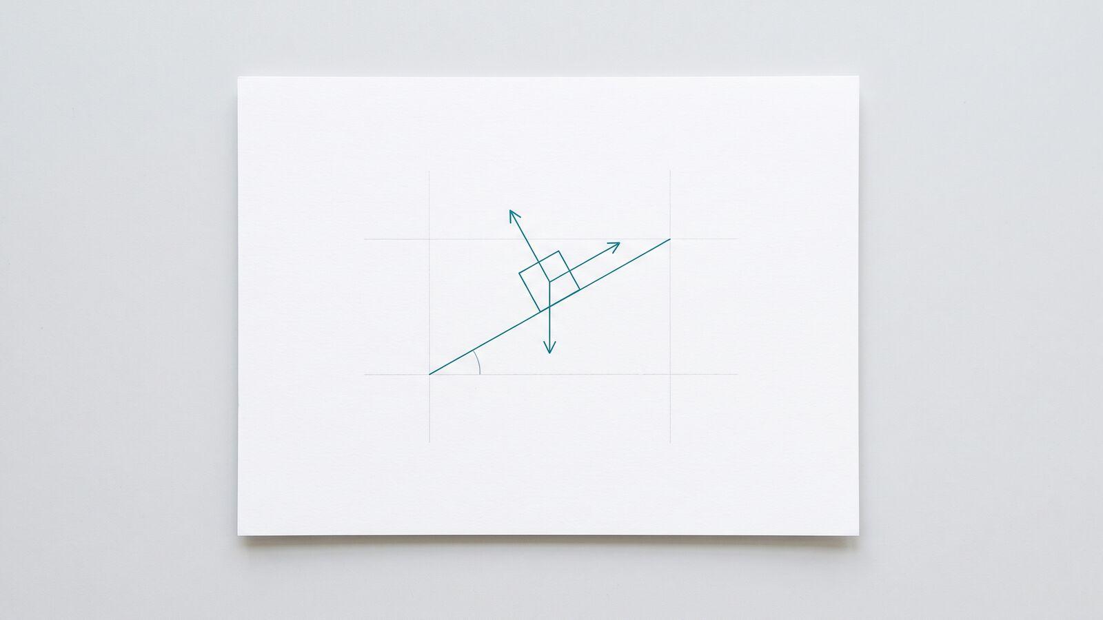
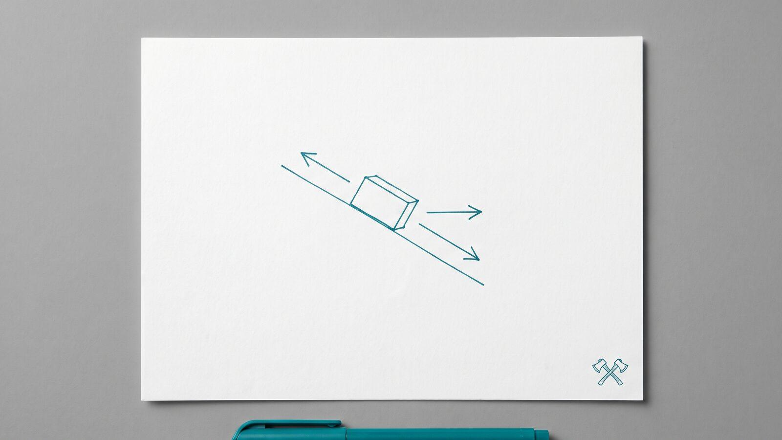
A block rests on a slope of angle . Forces: weight straight down, normal perpendicular to the slope, friction along the slope. Three arrows.
Axes along and perpendicular to the slope. The weight splits into down the slope and into the slope. Perpendicular:
Along the slope, for a block sliding down with kinetic friction,
which gives .
The most common error here is drawing the normal force vertically. It is perpendicular to the surface, which on a slope is not vertical, and that is exactly why is smaller than . The second most common error is mixing up sine and cosine in the components, which is a geometry check, not a physics one; our article on maths mistakes in physics shows how to settle it every time.
Worked case: a hanging mass on a string
A mass hangs from a string and is being pulled upward, accelerating at . Forces: weight down, tension up. Two arrows. Vertical axis, up positive:
so . If the mass were accelerating downward, would be negative and smaller than . If the string went slack, would be zero and the diagram would have one arrow.
Two forces, one line, and yet this diagram catches a persistent error: adding a downward "force of motion" when the mass moves down. Motion is not a force. The mass moves down because the weight exceeds the tension, and the diagram already contains both.
The five mistakes examiners see most
- Including net force as an arrow. The net force is the sum of the arrows you drew, not an extra one. Drawing it double-counts.
- Including centripetal force as an arrow. In circular motion, the inward force is provided by real forces already on the diagram, such as tension or friction. Our circular motion guide shows how to read them. Do not add a separate "centripetal" arrow.
- Drawing velocity or acceleration as forces. Neither is a force. If you want the acceleration on the page, put it beside the diagram in a different style.
- Forgetting a contact. Every surface, rope, and hand that touches the object exerts a force. Walk around the object and list the contacts before drawing.
- Drawing the normal force vertical on a slope, or friction perpendicular to the surface. Normal is perpendicular to the surface; friction is parallel to it. Say those two sentences aloud before drawing either arrow.
A checklist you can run in thirty seconds
- One object, drawn alone, named.
- Weight from the Earth, straight down.
- One normal force per surface, perpendicular to that surface.
- Friction parallel to each rough surface, opposing sliding.
- Tension along each rope, pulling away.
- Any applied force at its stated angle.
- No net force, no centripetal force, no velocity, no acceleration arrows.
- Axes along the acceleration or the surface.
- One second-law equation per axis, minus signs for negative directions.
Practice this in Physics Zen's dynamics topic, where the Newton's laws, friction, and inclined plane skills give you a fresh setup each time and check the force equations, then carry the same method into the circular motion topic where the diagram is the only thing that keeps the inward force honest.
A free-body diagram is not a formality before the real work. It is the real work. Draw it properly and the physics problem becomes an algebra problem, which is a much easier kind to have.
Common questions
- What is a free-body diagram?
- A free-body diagram is a sketch of one object, drawn on its own, with every force acting on that object shown as an arrow starting at the object. It leaves out the surroundings and the forces the object exerts on other things.
- Which forces go on a free-body diagram?
- Only real forces that act on the chosen object: weight, normal forces, friction, tension, applied pushes or pulls, spring forces, drag, and so on. Do not include net force, centripetal force, velocity, or acceleration as separate arrows.
- Does velocity belong on a free-body diagram?
- No. Velocity and acceleration are not forces. If it helps, draw the acceleration as a small labelled arrow beside the diagram, clearly separate from the force arrows, but never as one of them.
- Which direction does the normal force point?
- Perpendicular to the surface, pushing away from it. On a flat floor it points straight up. On an incline it points perpendicular to the slope, not vertically, which is why it is smaller than the weight on a slope.
- How do I choose the axes?
- Put one axis along the direction the object accelerates, or along the surface for an incline. Then most forces lie along an axis and only one, usually the weight, needs resolving into components.