Kirchhoff's Laws Explained: Junction and Loop Rules with Examples
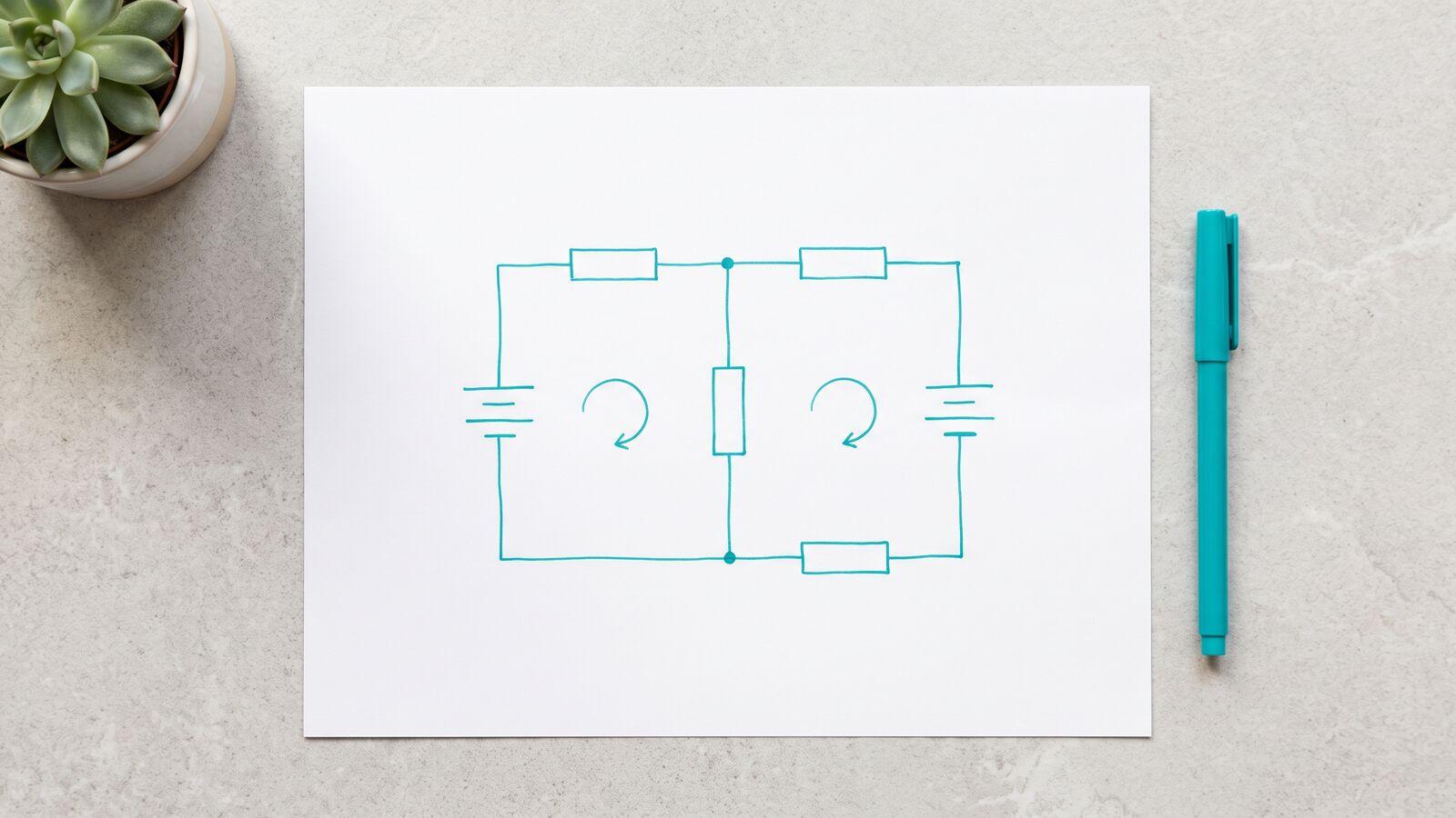
Two batteries, three resistors, and a question: which way does the current flow through the smaller battery? Most students draw an arrow out of its positive terminal, because that is what batteries do. In the circuit below that guess is wrong, and the algebra says so by handing back a negative number. Reading that minus sign correctly is most of what Kirchhoff's laws ask of you.
This guide states the two rules, gives one table of crossing signs, and then works a two-loop circuit with one current deliberately guessed the wrong way. It finishes with a bridge circuit, the classic case where series and parallel reduction cannot start. Everything uses ideal wires, ideal batteries with no internal resistance, and steady direct current.
The junction rule is charge bookkeeping
A junction is a point where three or more wires meet. Kirchhoff's first law, the junction rule or current law, says that the total current flowing into a junction equals the total current flowing out:
OpenStax's chapter on Kirchhoff's rules grounds this in conservation of charge: current is a flow of charge, charge does not pile up in a wire, so whatever arrives at a junction must leave it. If 3 A arrives along one wire and 2 A leaves along another, the third wire carries 1 A out.
You can apply the rule at every junction, but in a circuit with junctions only of the equations are independent. The last one repeats information you already have.
The loop rule is potential bookkeeping
Kirchhoff's second law, the loop rule or voltage law, says that if you walk around any closed loop and add up every change in electric potential, the total is zero:
You end at the point where you started, and a point has one potential. OpenStax links the rule to energy: whatever energy a source supplies to charge going around the loop, the devices in that loop transfer onward.
The rule is simple. The signs are where marks are lost, so fix them once:
| You cross | Direction of travel | Change in potential |
|---|---|---|
| Resistor | same way as the assumed current | |
| Resistor | against the assumed current | |
| Battery | from − terminal to + terminal | |
| Battery | from + terminal to − terminal |
These are the same four rules OpenStax gives. Two things to notice. The resistor sign depends on the current arrow you drew, not on the true current, which you do not know yet. The battery sign depends only on which terminal you meet first, never on the current through it.
A two-loop circuit with one wrong guess
Picture two horizontal wires, a top one joined at node A and a bottom one joined at node B. Three vertical branches connect them:
| Branch | Contains (bottom to top) | Assumed current |
|---|---|---|
| Left | 12 V battery, + side up, then a 2 Ω resistor | , upward into A |
| Middle | 3 Ω resistor | , downward out of A |
| Right | 3 V battery, + side up, then a 3 Ω resistor | , upward into A |
The arrows for and both point out of the positive terminals. That is the natural guess and, for the 3 V battery, the wrong one. Do not try to avoid it. The method handles it.
Junction A. Two currents in, one out:
Left loop. Start at B and go up the left branch, across the top to A, then down the middle branch to B. Crossing the 12 V battery from − to + gives . Crossing the 2 Ω resistor along gives . Going down the middle along gives :
Right loop. Start at B, go up the right branch to A, then down the middle:
Three unknowns, three independent equations. Now solve.
Solve, then read the sign
The right loop simplifies to , so . Put the junction equation into the left loop, replacing with :
Substitute :
Then and .
The minus sign on is the whole lesson. The magnitude, 1 A, is right. The direction is opposite to the arrow: current flows down through the right branch, entering the 3 V battery at its positive terminal. OpenStax says exactly this: a current assumed in the wrong direction comes out negative, and the answer is still correct.
Two habits keep the sign from biting you:
- Do not flip the arrow and start again. The equations were built on your arrows, and they are consistent with them.
- Carry the negative value into every later step. gives 3 A only if goes in as . Dropping the sign gives 1 A, and the error spreads.
Physically, the 12 V battery is driving current backward through the 3 V battery. A rechargeable cell in that position would be charging. If the solving step itself feels slippery, our guide to physics mistakes that are really math mistakes has a section on two unknowns and simultaneous equations.
Check it twice: node voltage and power balance
Node voltage. Every branch connects A to B, so each one must give the same potential difference . Middle: . Left: the battery raises the potential by 12 V and the resistor drops , leaving 6 V. Right: . Three branches, one answer.
Power balance. OpenStax recommends checking a Kirchhoff solution by comparing the power the sources supply with the power the other elements take. Here:
| Element | Power |
|---|---|
| 12 V battery, 3 A out of + terminal | supplies |
| 2 Ω resistor, 3 A | |
| 3 Ω middle resistor, 2 A | |
| 3 Ω right resistor, 1 A | |
| 3 V battery, 1 A into + terminal | absorbs |
Supplied: 36 W. Taken: 18 + 12 + 3 + 3 = 36 W. The check balances only if the 3 V battery is counted as absorbing power, which is the negative current again, now in energy terms. Had you read as +1 A, the books would be off by 6 W.
When series and parallel reduction is enough
Our series and parallel circuits guide reduces a network step by step: find two resistors that share one unbranched path or the same two nodes, combine them, repeat. When that works, use it. It is Kirchhoff's rules already applied for you.
It stops working in two situations. The first is the circuit above: with a battery in two different branches, no pair of branches can be combined into a single resistor. The second is a bridge. Connect a 12 V source between nodes A and B. A left arm goes from A through 1 Ω to node C, then through 4 Ω to B. A right arm goes from A through 4 Ω to node D, then through 1 Ω to B. A 2 Ω bridge resistor joins C and D.
No two resistors here share both endpoints, and none sit alone on an unbranched path, so reduction has nowhere to start. OpenStax notes that many circuits are like this. Write the junction rule at C and at D instead, with B at 0 V:
The solution is and . So 2 A crosses the bridge from C to D, the source delivers 6 A, and the network acts as 2 Ω. Check at C: 4 A arrives through the 1 Ω resistor, 2 A leaves through the 4 Ω resistor and 2 A through the bridge.
The tempting shortcut is to ignore the bridge and treat the arms as two 5 Ω paths in parallel. That gives 2.5 Ω and 4.8 A, which is 20 percent short of the real 6 A. The shortcut is valid only when the bridge is balanced, meaning the arms divide the voltage in the same ratio, so C and D sit at the same potential and no current crosses. Here the left arm puts its 1 Ω on top and the right arm puts its 4 Ω on top, so the ratios are inverted and the bridge carries current.
Two practice circuits, with answers
1. Both batteries discharging. Use the two-loop layout above with a 12 V battery and 3 Ω resistor in the left branch, 2 Ω in the middle, and a 9 V battery with a 3 Ω resistor in the right branch, both + sides up. Find all three currents and check the power. Answers: , , , all in the directions of the original arrows, and . Power: supplied, in the resistors.
2. A balanced bridge. Same bridge shape at 12 V, left arm 1 Ω then 2 Ω, right arm 2 Ω then 4 Ω, any bridge resistor. Find the bridge current and the source current. Answers: , so the bridge carries 0 A; the arms are 3 Ω and 6 Ω in parallel, 2 Ω in total, and the source supplies 6 A. Here, and only here, dropping the bridge is allowed.
Practise until the signs are automatic
The method does not change from circuit to circuit: arrows first, junctions, loops with the sign table, solve, read the signs, check with power. What changes is how quickly you can do it without hesitating over a minus. Kirchhoff appears on the electricity unit of our A-Level physics study plan, and the same habits carry over to capacitor networks, where our capacitors in series and parallel guide uses charge conservation at a junction in the same way.
In Physics Zen, the Circuits topic builds up through Ohm's law, series and parallel, and electrical power to a Kirchhoff's Rules skill with two-source circuits. That skill is part of Premium on iPhone and Android. Each problem comes with fresh values, instant checking, and a worked solution, so you can practise reading a negative current until it stops feeling like a mistake.
Common questions
- What are Kirchhoff's two laws?
- The junction rule (current law) says the total current entering a junction equals the total current leaving it, because charge is conserved. The loop rule (voltage law) says the changes in potential around any closed loop add to zero.
- What does a negative current mean in a Kirchhoff problem?
- It means the real current flows opposite to the arrow you drew. The size is still correct. Keep the negative value in every later equation and only reinterpret the direction at the end.
- How many equations do I need?
- One per unknown current. Use the junction rule at all junctions but one, then add loop equations until the count matches. Extra equations from the same loops are not independent and will not help.
- When do I need Kirchhoff instead of series and parallel rules?
- When the circuit has sources in more than one branch, or a bridge where no two resistors share both endpoints or a single unbranched path. If series and parallel reduction works, it gives the same answer faster.