Thin Lens Equation Examples: Real and Virtual Images
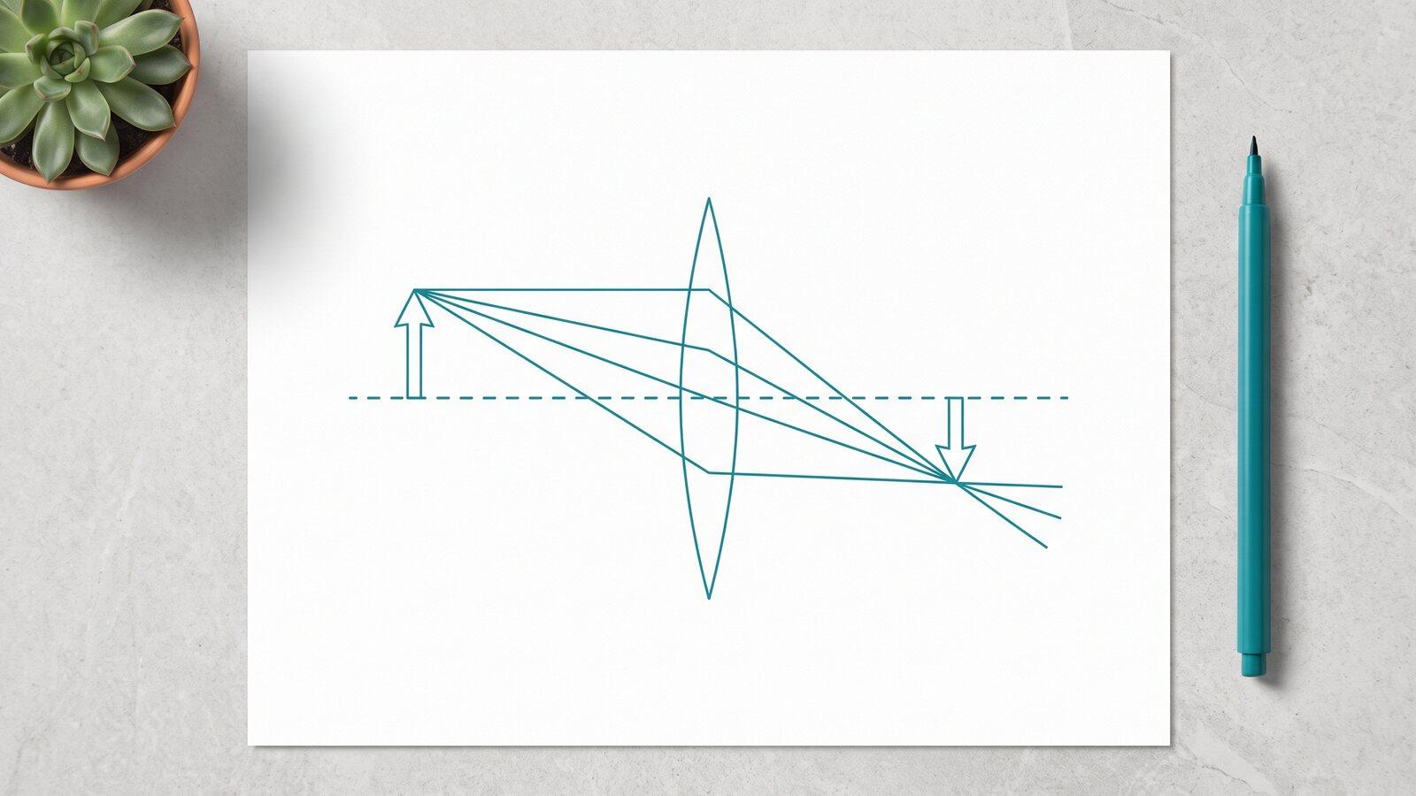
Put an object in front of a converging lens and move it toward the glass. At some positions you can place a screen on the far side and see a sharp image. Move the object closer than the focal length and the screen no longer catches one. Look through the lens, however, and the object can appear enlarged. The thin lens equation describes both cases, provided the signs describe which side of the lens the rays actually meet, or seem to meet.
The arithmetic is short. Most errors arise earlier, when a sketch is missing, a virtual image is assigned a positive distance, or a magnification sign is treated as a size. We will use one explicit convention from start to finish and check each answer against a ray picture.
Sketch the lens before choosing signs
Draw a horizontal principal axis and a vertical line for the lens. Place the object on the left. In the situations below, light travels left to right. Mark a focal point a distance from the lens on each side. This simple sketch gives you a place to put the image after solving.
For a converging lens, a ray from the object's top travelling parallel to the axis emerges toward the far focal point. A ray through the lens center continues approximately straight in the thin-lens model. Where those outgoing rays cross is a real image. If the outgoing rays spread apart, extend them backward with dashed lines. Their backward extensions meet at the virtual image; no actual outgoing light meets there. A diverging lens makes a parallel incoming ray spread as though it came from the near focal point.
These are idealized rays. A lens has thickness, and actual imaging can depart from the thin, paraxial approximation. The equation and sketches here assume rays close to the principal axis and small angles. OpenStax's thin lenses section sets out the equation, ray constructions, and convention used here.
The equation and one sign convention
Let be the object distance from the lens, the image distance, and the focal length. Then
All three distances must use the same unit. Centimetres work if every distance is in centimetres; metres work if every distance is in metres. The result inherits that unit. To solve for image distance, rearrange before entering numbers:
We use the real-is-positive convention for an ordinary real object on the incoming-light side:
| Quantity | Positive | Negative |
|---|---|---|
| Real object, as in every example here | Virtual object, outside this lesson | |
| Converging lens | Diverging lens | |
| Real image on the far side | Virtual image on the object side |
Some courses use a Cartesian coordinate convention with different signed positions. Do not transfer signs between conventions halfway through a calculation. If your course writes a different equation, use its definitions consistently. The physical questions remain the same: which way do the rays travel, where do they meet, and which way is the image oriented?
Worked example: a real image from a converging lens
Place an object in front of a converging lens with . The object is farther than one focal length, so a real image on the far side is plausible. Substitute :
Therefore . The positive sign puts the image on the far side of the lens. Check by substitution: . On your sketch, the parallel ray refracts through the far focus and the center ray crosses it there. The image is real, so an ideal screen placed at that plane can intercept the converging rays.
The image is smaller and inverted. To calculate that rather than guess, use magnification.
Magnification: separate orientation from size
With this same convention, the signed transverse magnification is
where and are object and image heights measured from the principal axis. A negative means inverted; a positive means upright. The absolute value is the image-height scale factor. It is not a length and has no unit.
For the first lens, . A tall object would have . The sign says its top appears below the axis, and its height magnitude is . Do not describe a negative height as a physically negative size.
Worked example: a virtual, enlarged image
Keep a converging lens with , but place the object only away. Because , the outgoing rays diverge. Their backward extensions meet on the object's side. Predict before calculating:
The virtual image lies from the lens on the object side. Magnification is
So the image is upright and three times the object's height in this ideal model. No screen at the virtual-image location can catch a bundle of rays forming that image there; the location comes from extending outgoing rays backward. This is the key difference between seeing a virtual image and projecting a real image onto a screen.
Worked example: a diverging lens
Now use a diverging lens with . Put a real object in front of it. The negative focal length is essential; using would describe a different lens.
Thus , a virtual image on the object side. The magnification is : upright and one-third as tall. In the sketch, rays leaving the lens spread apart. Their backward extensions intersect between the lens and its near focal point. Check the equation with the signs still attached: .
For a real object and a simple diverging lens in this model, you can expect a virtual, upright, reduced image. The calculation above shows that pattern for one set of distances; the negative is what drives it.
What happens at the focal plane?
In the rearranged equation , the denominator approaches zero as a real object approaches the focal distance of a converging lens. From just outside , grows large and positive. From just inside, it grows large and negative. Exactly at , : the outgoing rays are parallel in the ideal model, and there is no finite image distance to report.
Do not type into the fraction and call the calculator's division error a physical result. Draw the parallel rays and state that the image is at infinity in the ideal model.
Three problems to try, then check
1. Real image and height. A converging lens has . A tall real object stands away. Find image distance and height. Calculation: , so . Then and . The real image is inverted and half as tall.
2. Inside the focal length. A converging lens has and a real object at . Find the image and magnification. Calculation: , so . Then . The image is virtual, upright, and enlarged.
3. Diverging lens. A real object is from a lens with . Find image distance and type. Calculation: , so . Because it is on the object side, the image is virtual. Also , so it is upright and reduced.
Lens behavior begins with light changing direction. Our Snell's law guide explains refraction at one boundary. For lens calculations and image-type practice, try Physics Zen's optics topic. The A-level physics, Abitur physics and bac physique guides place optics in a wider revision plan.
Common questions
- Is image distance negative for a virtual image?
- Yes, under the real-is-positive convention used here. A negative image distance says the image is on the object side of the lens, where the light comes from. Check your course's convention before assigning signs to its equations.
- Can a converging lens make a virtual image?
- Yes. Place a real object closer to the lens than its focal length. The outgoing rays diverge, and their backward extensions form a virtual, upright, enlarged image on the object side.
- Does a negative magnification mean the image is smaller?
- No. The sign of the magnification describes orientation: negative means inverted, positive means upright. Compare the absolute value with 1 to decide size: above 1 is enlarged, below 1 is reduced.
- Why do I get no finite answer when the object is at the focal point?
- In the ideal thin-lens picture the rays emerge parallel. The equation gives 1/d_i = 0, so there is no finite image plane and the image is said to be at infinity. This is a useful limit check, not a missing minus sign.